Received: Tue 15, Aug 2023
Accepted: Thu 21, Sep 2023
Abstract
‘In vivo’ studies pertaining to dynamics of vocal fold vibration motion, to vocal fold contact and collision, to vocal onset and offset and to mechanical efficiency all need valid, sensitive and precise measurements of the different mechanical parameters involved. This is also true for investigating the physiological correlates of particular acoustic events like register breaks or diplophonia. The main physical parameters involved are: vocal fold movement and shaping, particularly the velocity of tissue displacement, glottal area, tissue distortion, intraglottal pressure, transglottal air flow, vocal fold contact and collision stress, etc. This article presents a critical review of the instruments and techniques involved in the direct measurements of the glottal dimensions and movements, the transglottal airflow, the VF contact changes, the pressures and the sound acoustic pressure. In each case are analyzed the methodological aspects that are critical for validly calibrating and synchronizing these signals, and correcting them for time delays. Moreover, it is shown how new parameters, like vocal fold velocity, intraglottal pressure, vocal fold collision stress, can be inferred from these (raw or after differentiation) signals by combining them. Finally, the discussion focuses on weighing advantages and limitations of techniques for monitoring the glottal area, i.e. photometry and the high-speed imaging, the latter involving the relevance in this scope of future developments in endoscopic and external imaging techniques, and in image processing software. Our aim is to facilitate the work of future researchers by showing how to solve important technical pitfalls, how to apply the necessary corrective measures - and which ones - where needed, and how to get the most out of combinatorial measures.
Keywords
Phonation, glottal dynamics, vocal fold mechanics, videokymography, high-speed imaging
1. Introduction
Since the pioneer work of Ishizaka & Flanagan [1], Titze [2] et al., studies of vocal fold (VF) mechanics based either on (in vitro) mechanical experiments or on computer and mathematical modelling have flourished, particularly in the last two decades. They have made important contributions not only to a more in depth understanding of the basic physiology of the human voicing, but also to an innovating insight in the pathogenesis of some disorders and of their prevention [3, 4].
As a matter of fact, ‘in vitro’ and modelling studies can be partially explained by the difficulty of a non-invasive ‘in vivo’ approach: direct measurements indeed require a specific technical expertise. Moreover, due to the necessary skilled voluntary control of respiratory and voicing characteristics (pitch, loudness, stability, specific vocalizations etc.), only few well-trained vocalists appear to be suited for such experiments [5]. However, all these obstacles are not insurmountable. In this article, we present an overview of the issues related to technical expertise and to adaptations, calibrations, control and corrections (time) required to obtain valid synchronous recordings.
‘In vivo’ studies pertaining to dynamics of vocal fold vibration motion, to vocal fold contact and collision, to vocal onset and offset and to mechanical efficiency all need valid, sensitive and precise measurements of the different mechanical parameters involved. This is also true for investigating the physiological correlates of particular acoustic events like register breaks or diplophonia. The main physical parameters involved are: vocal fold movement and shaping, particularly the velocity of tissue displacement, glottal area, tissue distortion, intraglottal pressure, transglottal air flow, vocal fold contact and collision stress, etc. [6-11]. Figure 1 illustrates a schematic configuration of an exemplative experimental setup, as used by the authors (translaryngeal impedance electrodes have been omitted).
The intraglottal pressure is the driving force of vocal fold vibration [12]. When correlated with VF motion, it is the key parameter for understanding VF biomechanics. Owing to their technical difficulty, direct experimental recordings of the intraglottal pressure (or even subglottal or supraglottal pressure) with respect to glottal dynamics during the vibratory cycle are very scarce in the literature. Indeed measuring directly the subglottal pressure requires either a tracheal puncture or a transglottal pressure pressure catheter, and any intraglottal foreign body may interfere with spontaneous voicing [11].
However, as outlined by Titze [3, 12], when the area curves and the airflow curves are accurately displayed, the cyclic velocity of the air particles can be easily calculated, and in turn - by using the principle of energy conservation - the intraglottal pressure during the open phase of the vibration cycle can be inferred by calculation. This methodology can be applied in in vivo measurements, as it is noninvasive, and makes possible real time correlations with other parameters either during steady state phonation in controlled conditions, or for investigation of specific events, like vocal onset. In the present work, we critically review the instruments and the methodology we have used in our last studies, including relevant remarks and advices of reviewers.
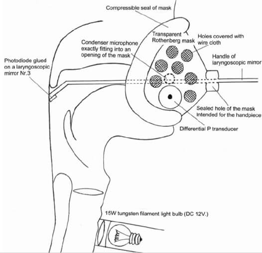
The section ‘Material’ describes the instruments and techniques involved in the direct measurements of the glottal dimensions and movements, the transglottal airflow, the VF contact changes, the pressures and the sound acoustic pressure. The section ‘Results & Discussion’ reports about the methodological aspects that are critical for validly calibrating and synchronizing these signals, and correcting them for time delays. Moreover, it is shown how new parameters, like VF velocity, intraglottal pressure, VF-collision stress, can be inferred from these (raw or after differentiation) signals by combining them. Finally, the discussion focuses on weighing advantages and limitations of techniques for monitoring the glottal area, i.e. photometry and the high-speed imaging, the latter involving the relevance in this scope of future developments in endoscopic and external imaging techniques, and in image processing software.
2. Material
The main instrumentation for investigating glottal dynamics during phonation consists in:
Morphometric techniques: high speed videolaryngoscopy, videokymography (single line scan), photoglottography. Videolaryngostroboscopy (which is the gold standard in clinical work, and the basic reference [13], will not be discussed here),
Flow glottography (Rothenberg’s mask),
Pressure sensors (Millar catheter),
Electroglottography (translaryngeal electrical impedance),
Ultrasound glottography,
Audio-recording.
2.1. Glottal Quantitative Morphometry
2.1.1. High Speed Video and Videokymography (Single Line Scanning)
High speed video [14-18] requires laryngoscopy with an endoscope capable of delivering sufficient illumination (Xenon lamp 300W) for frame rates 2-4 kHz with a resolution of 2000 × 2000 pixels. A rigid 90° noninvasive endoscope is best suited, but major current improvements in light intensified digital imaging systems make it possible to acquire high speed video recordings of vibrating vocal folds through a flexible transnasal endoscope (diameter 3,4 mm). Even if ‘chip-on-tip’ systems (1280 × 800 pixels) outperform traditional fiberscopes, the image resolution is lower than that obtained with rigid scopes, but it may be sufficient if the tip of the catheter can be positioned close to the vocal folds. However, some distortion of the image cannot be avoided [19, 20]. Colour (implying a 4-times reduction of the maximum frame rate relative to monochrome for the same image quality) is usually not necessary for physiological research, contrary to clinical applications [16, 17]. Compared to transoral rigid endoscopy, a flexible fiberscope makes it possible to observe a more natural laryngeal function over a wider range of speech (and non-speech) tasks, instead of only sustained sounds.
High-speed single line scanning of VF vibrations is an imaging method (videokymography) based on a special digital camera, which is fixed on a rigid 90° 4450.57 Wolf laryngeal telescope with focusing handle [21, 22]. In the high-speed mode, the video camera delivers images of a single line selected from the whole image, at the rate of approximately 7875/7812.5 line-images per second and 720 × 1/768 × 1 pixels resolution. The resulting high-speed image, also called “videokymogram,” displays the vibratory pattern of the small selected part of the VF cycle by cycle. Such a recording is divided into video frames (i.e., segments of approximately 15/18 ms duration with time on the vertical axis). When correctly applied, this technique allows a clear visualization of some basic physiological parameters of VF vibration: periodicity, duration of opening, closing and closed phases, amplitude of the vibration, and right-left symmetry (Figure 2).
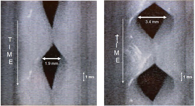
Videokymography has been successfully applied to voice pathology, particularly in situations where the traditional videostroboscopy is failing as in the case of very irregular vibrations, when the VF do not vibrate at the same frequency, or in the case of short “accidents” (e.g., register breaks). High speed imaging coupled with an analysis programme [23] Laukkanen, Geneid et al. has made measurements of glottal area parameters much easier.
2.2. Photoglottography (PGG) [24-26]
The glottal area can be derived from a photometric record, obtained by transilluminating the trachea. The light flux is detected by a photovoltaic transducer in the pharynx. The transducer, a BP104 silicon photodiode (Vishay Precision Group, Malvern, PA), is glued onto a small laryngoscopic mirror (Nr. 3) (Figure 1). The current produced by the photodiode is preamplified by a current-to-voltage converter with a linear and flat frequency response up to 2 kHz. During VF vibration, the photovoltaic transducer produces a current which is directly proportional to the light flux through the glottis, thus to the glottal area.
2.3. Electroglottography (EGG)
Electroglottography measures the transglottic electrical impedance using an AC current at a frequency above 100 kHz and monitors the changes in contact surface of the VF. The method is patient-friendly and does not interfere with vocalization. It allows precise phonetic tasks, with acoustic control [25]. The EGG-signal, used as a reference for monitoring the contact surface changes, can easily be detected using a portable electroglottograph (Laryngograph Ltd, London, UK) Model EG90. However, the sensitivity for detecting very small transglottic impedance changes (essential in this context) depends on the design of the electronic circuit. The original design of Fourcin and Abberton (1972) [27] has been superseded by more recent devices using a higher carrier-wave frequency, a more efficient feed-back control of the oscillator, multipole filters with sharper cut-off and flat bandwidth response (e.g., F-J Electronics, Denmark; Laryngograph, UK; SynchrovoiceResearch, USA; etc.). As a result, a better signal-to-noise ratio and a higher sensitivity are achieved with a larger bandwidth and better linearity [28]. As shown in an earlier work [9], the EGG-signal can be as sensitive as the flowglottogram for detecting very small vocal fold oscillations, but, contrary to the flow signal, it may fail to show the very first movements when there is no contact between the VF. These tiny sinusoidal EGG-cycles probably correspond to small (reduced amplitude) periodical impedance fluctuations at the level of the sharp angle of the VF commissure.
2.4. Flow Glottography [29-33]
The Rothenberg ‘flow-glottograph’ is a high-speed pneumotachograph (a fast-responding differential pressure transducer). It consists in a specially designed mask (Figure 1) and an inverse filtering system. The ‘Rothenberg mask’ (MSIF2 Glottal Enterprises (Syracuse, NY) is widely used to analyze the source of voiced speech and the glottal volume velocity waveform. The effects of vocal tract resonances can be cancelled by filtering the oral airflow recorded at the lips. The mask is equipped with a compressible seal and simply needs to be firmly pressed against the face of the subject to prevent any air leakage.
2.5. Ultrasound Glottography [34, 35]
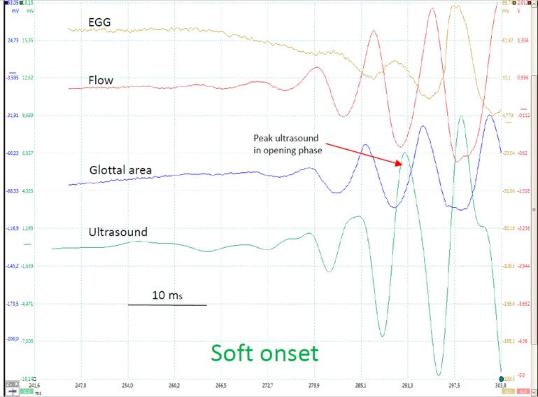
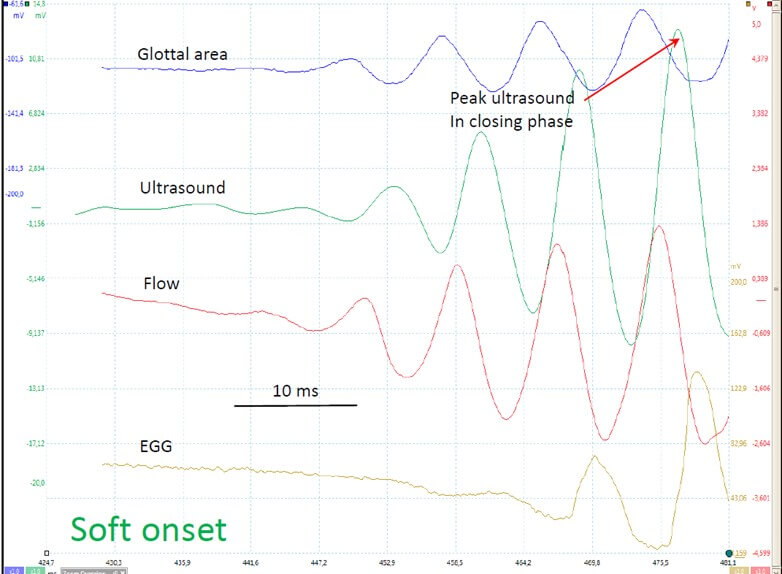
The Terumo UTD-6 Doppler ultrasound flowmeter (TERUMO AMERICA, INC 803 N. Front St. Suite 3 McHenry, IL 60050) has been developed to measure the velocity of blood in vessels. The ultrasound signal is reflected by a vibrating VF with a ‘Doppler shift’ that depends on the vibration velocity. Its main advantage is that it is totally non-invasive. A very clear, noise-free signal directly related to glottal vibrations can easily be obtained. However, the positioning of the probe with respect to the larynx is extremely critical, and hardly reproducible from one recording session to another. Furthermore, the precise anatomical structure, as well as its face/side, that reflects the ultrasonic beam cannot be determined and thus the signal cannot be calibrated with respect to the glottal movements. It is even impossible to determine if the movement is an opening or a closing one (Figures 3 & 4). The main advantage of the technique is its high sensitivity in detecting very small VF movements, e.g., at the very initial start of VF oscillation onset, which may be an important research parameter to be correlated with other measures. In our experience, the ultrasound signal is as sensitive as (but not more sensitive than) the photoelectric signal.
2.6. Pressure [36-38]
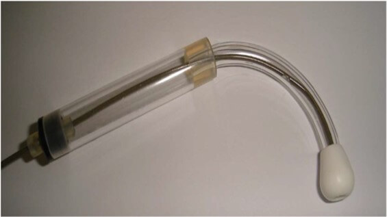
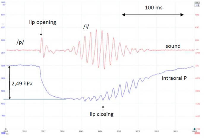
A thin millar-catheter (like the semi-rigid SPC-751 model, diameter 1,5 mm) is theoretically well suited, particularly considering its sensitivity 37,6 µV/V/kPa and its frequency response of DC to 1 KHz (-3 dB) for a direct measurement of the instantaneous intraglottal / subglottal pressure. However, the intraglottal introduction, via the dorsal part of the glottis is invasive, requiring a topical anesthesia. Moreover, a precise control of the position of the tip with the lateral sensor during phonation is impossible, and the slightest contact with the mucosa of the subglottis or trachea-wall immediately generates major artifacts. Only a central floating position provides a correct signal, but it mechanically interferes with the VF vibration. Hence, for the instantaneous measure of the intraglottal pressure, the solution is to compute it from the combination of the instantaneous flow and area measurements at the glottal level. However, the value of the average lung pressure during vocal emissions or at specific moments, such as like voice onset, is also of major importance. For this purpose, the short flow interruption method can be applied, using the properties of the Millar-catheter without any invasiveness. The intra-oral pressure is measured with a millar MikroTip catheter imbedded in a home-made device (Figures 5 & 6). Hertegard et al. found that the indirect measurements of subglottic pressure obtained using the short flow interruption method were highly correlated with the direct measurements obtained by tracheal puncture [38].
2.7. Sound Oscillogram and SPL
An exhaustive tutorial and guidelines on measurement of SPL in voice and speech experimentation have been provided by Svec & Granqvist [39]. In the case of a stand-mounted and head-mounted microphone, the SPL of vocal emissions always needs to be reported together with the mouth-to-microphone distance (usually 10 or 30 cm, depending of the type of experiment), and the stability of this distance needs to be permanently controlled if the subject is likely to make head movements. Therefore head-mounted microphones usually have to be preferred [40]. Calibration requires a sound level meter e.g., Wärtsilä 7178 (Wärtsilä Electronics, Helsinki, Finland). Specific Sound level measurement settings (like time weighting/averaging) should always be specified. The background noise levels should also be reported if relevant [41].
In experiments with a Rothenberg mask, SPL can be monitored by a small condenser microphone (Ø 5.6 mm) hermetically fixed inside the Rothenberg mask (Figure 1): it exactly fits into a hole of the mask on the opposite side to that of the pressure transducer. In our case, processing of the voice samples for SPL analysis was achieved using the PRAAT software (www.praat.org). The sample frequency is usually 44.1 KHz. The microphone sound levels must be calibrated with a sound level meter in a position corresponding to a direct measurement at a 10 cm distance from the lips. The exact moment chosen for the area and pressure recording can then be clearly identified on the sound recording, allowing a precise fit of the area/airflow curves with the dB (A) value.
In some experiments, it may be necessary to take into account, as for the pressure wave, a delay of propagation of the pressure wave in the vocal tract, which can significantly differ between subjects. A laryngeal fiberscope gives an acceptable approximation. For example, a distance of 16 cm can be observed from the glottis to both the pressure detector and the microphone in the Rothenberg mask. Considering that the speed of sound at sea level, 30°C, and 100% RH is 351 m.s-1, the delay due to propagation of the pressure wave is 0.455 ms. This means that all records must be corrected accordingly.
3. Results & Discussion
In ‘in vivo’ studies of VF dynamics, a distinction can be made between parameters that are directly - and simultaneously - measured, like flow and sound and parameters that are derived by computations based on the raw signals, like intraglottal pressure and glottal area. Moreover, some very interesting parameters can be obtained by derivation of some of the directy measured signals, like the maximum VF velocity and the maximum flow declination rate (MFDR).
All signals can be recorded through a four-channel analogue-to-digital converter PicoScope 2205A module (Pico Technology LTd, St Neots, England, UK) at a sampling frequency of typically 200 kHz per signal. For actual in vivo combined measurements, the practical difficulty is to succeed in obtaining (with adequate formant filtering) a flow signal with a closed plateau that is as horizontal as possible (without ripple), while simultaneously configuring the oropharyngeal tract in such a way that the glottal light signal is optimally detected by the photovoltaic sensor. As a matter of fact, the absolute magnitude of the light signal is critically influenced by the precise positioning of the sensor in the pharynx. Figure 7 illustrates an example. Nonoptimal positioning results in a low-amplitude, noisy signal, although its pattern remains unchanged. In practice, it is unrelated to SPL, contrary to the flow signal.
It is also possible to introduce a fiberscope through a hole in the Rothenberg mask. Another alternative is to introduce the photovoltaic transducer via the nose. Of course, as the most relevant information is provided by synchronous recording of different measurements, careful calibration of the direct measurements is essential and adequate correction of time delays is required for a precision of the order of 0.01 ms. The actual physiological findings resulting from the methodology explained here are reported in our cited publications.
3.1. Calibrations
3.1.1. Calibration of the Flow - Glottograph [7]
The Rothenberg mask is equipped with a compressible seal and is firmly pressed against the face of the subject to avoid any air leakage. By injecting air from an external source in the mask, saturation of the output of the filtering system was found to occur at flow values 20% larger than the largest values measured in the experiments. The system can be used to measure continuous air flows and thus it can be absolutely calibrated. To this aim, the mask was fitted onto a polystyrene dummy head such as those used in shop windows. A 3 cm diameter tube was inserted through the head at mouth level, and a controlled air flow was sent in the tube through a calibrated volumetric flow meter at a range of flow values. At each value of flow, the absolute value of the flow was measured using a calibrated pneumotachograph connected in series with the mask. The output of the Rothenberg processing unit was recorded. This was found to be linearly related to the air flow; the slope of the regression analysis of the results was 85.7 mL.S-1 /V. This slope of was then used to calculate absolute values of flow in our experiments.
3.1.2. Calibration of Light Flow Measurements [7]
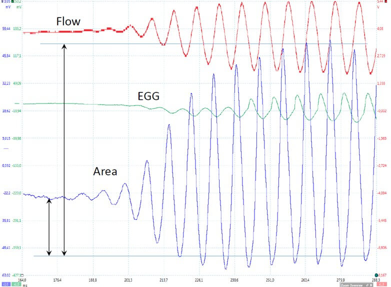
Contrary to the air flow, the flow of light through the glottis is difficult to calibrate. The reason is that the absolute value of light intensity detected by the photodiode in the pharynx is very sensitive to minute changes in its position relative to the glottis, and cannot be reliably maintained for more than the duration of one single vocal utterance. Consequently, only separated utterances can be recorded. However, it may be considered that within a short utterance, amplitudes - e.g., in an onset or an end of emission - can be validly compared. Depending on the type of research, light signals can be expressed as percentages of the maximum value of the signal, thus ranging between 0 and 100 % (Figure 8).
3.2. Correction of Instrumental Time Delays
In several studies, it is necessary to simultaneous record glottal area (photoglottography), glottal flow (flow-glottography) and vocal fold contact (electroglottography) usually together with the sound oscillogram. Figure 7 gives an example of such a record. In such cases, all signals have to be carefully lined up, and all instrumental delays must be corrected.
3.2.1. Correction of Instrumental Time Delay of the PGG Signal [7]
The instrumental delay of the PGG was evaluated as follows. A function generator (model 3311A, HPE, Palo Alto, CAL, USA) was used to produce calibrated sine waves added to a constant positive offset. This signal was fed to light up an LED placed in front of the detecting photodiode as used in the records. The aim of the constant base current was to keep the LED lit continuously, to avoid a possible threshold effect of the LED when applying low frequency sine waves. The light emitted by the LED was readily detected by the photodiode and the magnitude of the exciting currents was adjusted to produce photodiode signals of the same order of magnitude as those of signals from the glottis observed in our experiments. By displaying both the LED current and the photodiode output on the oscilloscope screen, the exact time delay of the whole chain of the PGG signal recording was measured over a range of frequencies from 80 to 220 Hz. The result was a systematic mean delay of 0.102 ms with no significant change over the tested range of frequencies, with an effective time resolution of 10 μs. All records are to be corrected for the delay.
3.2.2. Correction of the Experimental Time Delay of the Flow Signal [7, 29-31]
Rothenberg specifies, in the original papers describing the use of his flowmeter, that a constant correction of 1.25 ms must be applied to all records. The delay is the sum of two terms: delay in the electronic detection and preamplification circuit, and delay due to propagation of the pressure wave from the level of the glottis to the pressure detector inserted in the wall of the mask. The delay due to the electronic circuitry was measured by injecting calibrated signals at the input of the preamplifier, and a constant delay of 0.75 ms was found between the input and the output of the circuit, independent of frequency. In the subject tested in this work, a distance of 16 cm was measured from the glottis to the pressure detector. The speed of sound at sea level, 30°C and 100 % RH is 351 m.s-1, and the delay due to propagation of the pressure wave is thus 0.455 ms. All records are to be corrected for the total delay.
3.2.3. Correction of the Experimental Time Delay of the EGG Signal [42]
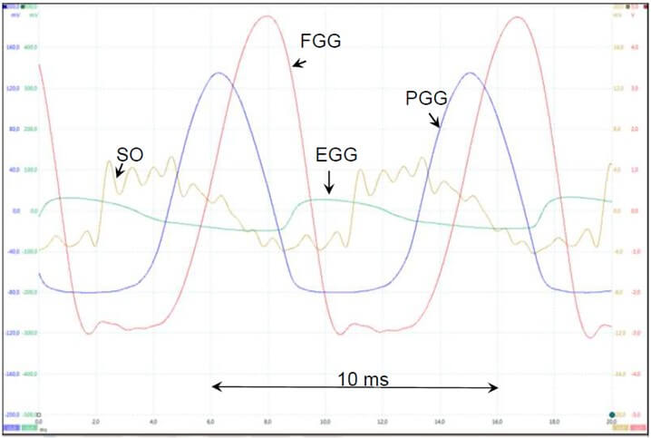
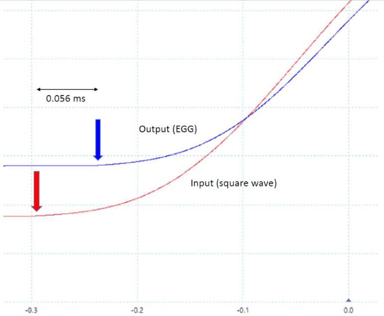
The absolute value of the translaryngeal conductance is an important piece of information which cannot be found in the literature. Values of the impedance of the larynx have been reported by Sarvayya et al. [28]. According to these authors, the impedance is purely ohmic for exciting current frequencies in the range 100 kHz to 1 MHz, and its value is typically in the range 100-500 ohms. Our EGG device (Laryngograph Ltd, London, UK, Model EG90) accepts values of source resistances in the range ~150 to ~500 Ω, rejecting other values. Thus, a 500 Ω calibrated potentiometer was connected between the electrodes and it was adjusted so that the EGG device was in the middle of its characteristics, around 250 Ω. Both rectangular and sine wave signals were applied. Likely due to complex multipole filters inside the circuit, the EGG output showed multiple oscillations when a square wave input was applied to the electrodes. For this reason, very smoothed rectangular waves had to be used instead, as shown, on an expanded time-scale, by the red curve in (Figure 9), which is a portion of a PicoScope screen. Only a portion of the record is shown on an expanded scale to evaluate the time delay. The blue curve shows the output signal of the EGG circuit, shifted to the right by 56 ms.
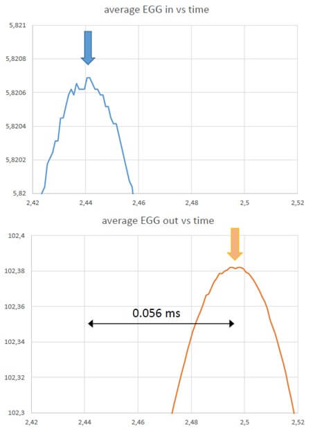
Hundred Hz sine-wave signals were also applied between the electrodes. Figure 10 shows the input and the output signals of such a sine wave on an expanded time-scale. To best evaluate the time shift between the input and the output, only the very expanded tips of the two sine waves are shown, so that noise becomes clearly visible on the trace, without affecting the resolution of the reading. As in the case of a smoothed rectangular input, the output is shifted by 56 ms relative to the input.
3.3. Computations
3.3.1. Computing the Intraglottal Pressure [7, 10, 12]
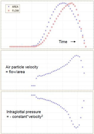
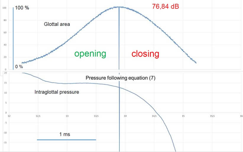
The intraglottal pressure P can be computed from the transglottal flow and the air particle velocity (= flow/area) on the basis of the Bernoulli energy law:
P + ½ρv2= constant
Where ρ is fluid density and v is particle velocity [7, 12] (Figure 11). However, when the glottis is open, the intraglottal pressure is affected by the supraglottal acoustic pressure, which modifies the overall pressure distribution in the glottis. Actually, the above equation is applicable for a convergent glottal duct, i.e., upstream of the glottal narrowing, while for a divergent glottal duct, i.e., downstream of the narrowing, where separation of airflow from the wall and vortices could occur, the inertance equation:
P = IdU/dt
Must be considered, where I is supraglottal acoustic inertance and U is airflow. The inertance of an air column is defined as the air density multiplied by the length of the column (along the direction of acceleration or deceleration) and divided by its cross-sectional area (perpendicular to the acceleration or deceleration). Inertance is the effect of inertia opposing the transmission of vibration through the supraglottal air column, i.e., a resistance to the movement. It can be calculated as [43]:
I = ρL/S
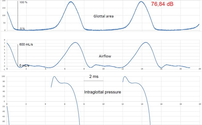
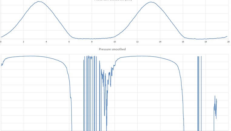
Where S is the cross-sectional area of the supraglottal air column and L is its effective length. Units are g. cm-4 or kg. m-4 (1 g.cm-4 = 105 kg. m-4). L and S may be considered constant during emission of a sustained vowel, as is the case in our experiments. However, this divergent shape of the glottal duct mainly appears at high subglottal pressures, when the vibration cycle is characterized by a long closed phase and a relevant phase difference between the lower and upper margins of the vocal folds. At low subglottal pressures, as during vocal onset, the vertical glottal duct is expected to be shorter [11, 44] and the shape differentiation (convergent / divergent) - including the phenomena of airflow separation from the glottal wall and of vortices formation - less pronounced than in sustained modal phonation, or even totally absent. Hence, we may reasonably assume that the average driving pressure (bottom to top) is close to the Bernoulli pressure, estimated numerically via the glottal area in the position where the glottis is the narrowest. It can be shown that, when the airflow curve is skewed to the right with respect to the glottal area curve, the intraglottal pressure during the opening phase exceeds that during the closing phase [7] (Figures 12 & 13). The skewing results from air compressibility and vocal tract inertance. The closed phase of the vibration cycle has no interest in this scope, and computing of intraglottal pressure does not make sense (Figure 14); defining the boundaries of open phase will be explained in next section.
3.3.2. Computing the Glottal Area [11]
As explained above, the light flux of the transilluminated trachea is detected by a photovoltaic transducer in the pharynx. Relative amplitudes of the oscillating signal are sufficient for some studies, e.g., dealing with damping, but for other experiments, absolute values of glottal area are indispensable, thus requiring a valid and precise calibration.
In research dealing with VF dynamics, the essential part of the vibratory cycle is the open part, comprising an opening and a closing phase. Hence the beginning of the opening phase and the end of the closing phase have to be clearly defined, as when both airflow and glottal area fall to near zero, their quotient, which is air velocity, becomes meaningless and thus unusable. We considered, according to the method of Gerratt et al. [24] that these boundaries occur when the rising and falling trace intersects a horizontal line drawn at 90% down from the positive peak. This line is parallel to a line drawn between the negative peaks preceding and following the positive peak of maximal opening. A fixed quantitative regression line between the current produced by the photodiode and the actual glottal area is impossible to obtain, as the current also depends to a large extent on the precise position of the photodiode in the pharynx, which varies from recording to recording. However, within a single, controlled voice utterance, the relation may be considered as linear and stable.
The precise position and orientation of the photodiode in the pharynx cannot be reproduced from record to record, which means that the amplitude of the absolute value of the photovoltaic current can vary from experiment to experiment, but not within a single voice utterance. For measurement of the glottal area and calibration of the photoglottographic signal, we first need to know the ventrodorsal length of the vibrating glottis, which may be assumed to be stable within the frequency range 100-125 Hz. This ventrodorsal length of the glottis during a vibration cycle is constant for a sustained modal phonation at controlled Fo, and can be measured (in mm) on a stroboscopic picture obtained in the same subject uttering a similar voice sound. In order to obtain this reference, a rigid 90° wolf laryngeal telescope (4450.57; CE 0124) and an ATMOS Strobo 21 LED stroboscope (Atmos Medizin Technik, Lenzkirch, Germany) were used. The telescope has a magnifying facility, with narrow depth of field and critical sharpness adjustment; scaled paper was filmed at the same focal length, critical care being given to maximal sharpness [6]. This way of proceeding is inspired by Fex et al. [45], who used a microscope, and calculated a maximal error of measurement of 4.65 +/- 3.10%. With our 90° telescope and the magnifying option, the range of sharpness was found to be at most 3-4 mm at a distance of 40-45 mm. In this way, the ventrodorsal length of the glottis was estimated to be 13 mm, in line with the values found by Larsson & Hertegard [46], who used a laser triangulation method. The light signal can be expressed as a fraction of the maximal amplitude at full opening (Figure 8).
In fluid mechanics calculations, an important issue is the ‘equivalent diameter’ (with respect to a cylindrical pipe) [47]. The shape of the glottis is not cylindrical; thus, an expression must be found to calculate an equivalent diameter of the glottis to be introduced in the adequate equations. To this aim, videostroboscopic recordings of the glottis of the subject were made in voicing conditions similar to those used for the aerodynamic measurements. A stroboscopic still image at the time of maximal opening during phonation (as soon as the stroboscope is triggered) provides an adequate measure of glottal dimensions at this critical time point. After calibration, the ventro-dorsal length of the glottis was found to be 13 mm and the maximal width was 3 mm, in line with the values found by Larsson & Hertegard [46]. We found that the contour of the glottal image could be quite well fitted with an ellipse, the major and the minor axes of which were respectively the ventro-dorsal length and the maximal width of the glottis picture. This is illustrated in (Figure 15). In this case, the difference between the calculated area of the ellipse and the measured area of the glottis is less than 1%. Using an ellipse to describe our recorded curves has the advantage that on the basis of the area of the glottis at the time of onset, given by the photoglottographic signal, and taking the constant ventro-dorsal length of the glottis (13 mm in our subject) as the major axis of the ellipse, the minor axis is easily calculated using the elementary formula of the area of the ellipse.

The equivalent diameter of an ellipse is given by: ed = 1.55 A 0.625 / P 0.25 where A and P are the area and the perimeter of the ellipse respectively. Several formulas are commonly used to calculate the perimeter of the ellipse, but they give an approximate result, usually valid within a limited range of ratios of the two axes of the ellipse, narrower than the values obtained for the glottis. We therefore preferred to apply an exact formula that uses an infinite series of terms. A convenient on-line calculation tool based on such a formula is available at the following website: (Link).
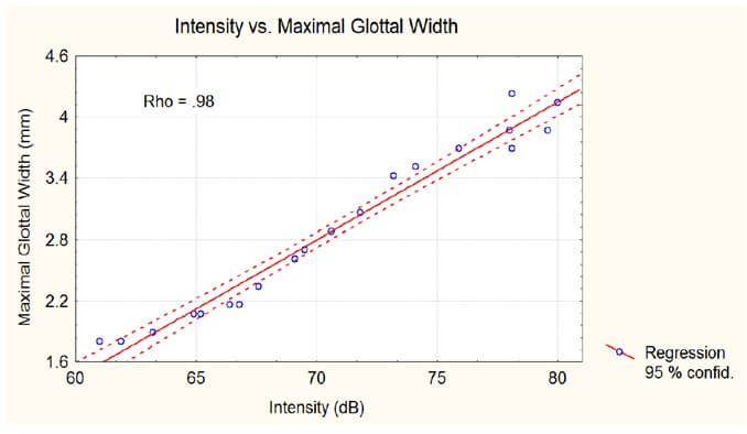
Contrary to the length, the maximal glottal width is strongly correlated (male subjects, breast register) with the intensity of voicing [6, 42] as shown in (Figure 16). The maximum glottal area is directly computed from the photometric signal, after calibration based on imaging, with a precision of 5%-10%. Determination of the maximum closing velocity uses the first derivative of the glottal area, which requires a high quality, noise-free signal and a high sampling frequency. In this scope, our photometric method far outperforms the imaging techniques. High-speed video images are limited by the number of pixels (resolution), but merely by the frequency of the measurement moments, as demonstrated by the experiments of Horacek et al. [48] in which, e.g., at 2.000 images/s, for a F0 of 100 Hz and a closed quotient of 0.5, only 5 points are measured during the closing phase.
3.3.3. Smoothing
In some cases of noisy records, typically PGG signals of small amplitude, the curves could be smoothed, for publication purposes, by replacing each sample of the record by the mean of 4 or 5 samples upstream and 4 or 5 downstream, thus providing a moving average. This has the effect of a low-pass filter masking high frequency noise.
3.4. Differentiations
3.4.1. Differentiation of the PGG Signal (for obtaining maximum VF velocity) [42]
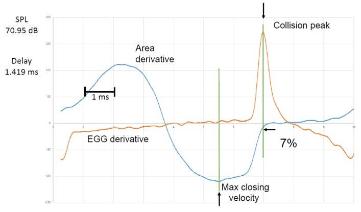
The amplified PGG signal has an intrinsic very high signal to noise (S/N) ratio, so that it can be differentiated without too much high frequency components. In the case of a sampled signal, such as our PGG signal, the closest approach to the true time derivative is given by the increment of the measured variable during the smallest increment of time. In other words, it is the difference between two successive samples multiplied by the sampling frequency. The drawback of applying this strictly is that it produces very large noise at high frequencies in which the significant changes are not visible. Therefore, a time constant is introduced in the form of averaging a number of samples. Moreover, it is preferable to calculate the average of an equal number of samples upstream and downstream relative to the considered sample in order to keep the derivative in phase with the signal. We tried averaging the smallest number of samples which gave a clear curve for the derivative. In practice, including 4 samples upstream and 4 downstream, or 9 samples in total, gave an excellent result in most cases, as illustrated in (Figure 17). Thus, the first-time derivative was computed by the following algorithm, given by the simple equation:
dy/dt(t) = (y (n+4) - y (n-4)) / (n+4 - n-4)
Where n is the serial number of the sample in the record. The computed derivative is thus exactly in phase with the signal. With a sampling frequency of 200 kHz, there are at least 2000 samples per phonatory cycle, or about 1000 points per open phase, an order of magnitude higher than the fastest sampling frequency of high-speed cameras, which does not provide a high S/N ratio. An example of such a derivative of the PGG signal is given in (Figure 17), simultaneously with the first derivative of the EGG signal computed using the same algorithm. Corrections of instrumental delays have been applied to both signals (0.102 ms and 0.056 ms). The arrows indicate the positive peak for EGG (i.e., the max. rate of increase in VF contact once the glottis is closed) and the negative peak for PGG (i.e, the max. glottal closing velocity).
3.4.2. Differentiation of the EGG - Signal
As for the photoglottogram, the very high sampling frequency makes it possible to accurately compute the first derivative of the EGG signal. An example of such a derivative is shown in (Figure 17). The positive peak of the EGG-derivative indicates the maximum rate of increase in VF contact (which may be considered as the collision peak).
3.4.3. Differentiation of the Flow-Glottography Signal
Owing to the multiple filtering in the processing unit in the rothenberg flowmeter, the flow signal has a good signal to noise ratio. Thus, its first derivative allows to precisely localize events within the cycle. One parameter which has been frequently used in the litterature is the maximal flow declination rate (MFDR) [49].
4. Additional Discussion Issues
4.1. Imaging vs. Photoelectric Method for Glottal Area
The relevance of a photometric technique vs. the analysis of high speed video is illustrated by recent work of Horacek et al. [5, 48]. The authors deal with the relation between the instant of maximal collision force of the VFs and their velocity. One experiment is made in vivo with a rigid endoscope and a frame rate of 2000 Hz (512 × 512 pixels): this provides only a few glottal area values (5 to 6) during the closing phase; the image-rate and the resolution of the high-speed camera are obviously too low for a really precise computation of the derivative and valid measurements of MADR as well as V0, and the authors mention it in their discussion.
In the other experiment, the authors make measurements on a physical model: a high-speed CCD camera (NanoSense MkIII, maximum resolution 1280 × 1024 pixels) fitted with a zoom lens (Nikon ED, AF NIKKOR, 70-300 mm, 1:4-5.6 D) is included in the measurement set up for investigating VFs’ vibration. The rate of image recording in a personal computer is 10,000 frames/s with the maximum possible resolution (548 × 104 pixels). The camera is positioned at a 90◦ angle of the trachea model where a glass window is installed; the difference in glottal area monitoring is obvious: a sufficiently large number of points is now available for a precise computation of VF velocity during the closing phase.
This demonstrates that so far, the noise-free photoelectrical device is the better tool when experimental conditions make it possible to use it, but it may be expected that, with conjunction of technological progress in as well as high-speed imaging and processing software, PGG, which by the way never reached clinical applicability, will become obsolete.
4.2. Precise Distance Measurements at Glottal Level
Another aspect is the need for spatially calibrated measurements. When employing a surgical endoscope (with an operating channel), a laser source that emits spatially coherent light can be used for creating fiducial patterns with specific topological properties [50]. The created pattern could then be delivered by coupling the laser projection component to an endoscope, or by using a surgical endoscope. It is noteworthy that optical coherence tomography is another imaging modality that could provide calibrated measurement capabilities. Two main approaches of parallel laser markers and multiple laser points have been used for creating the laser-fiducial markers in the field of voice. The projection of the parallel laser markers is the simplest approach. Two-point laser projection, two-line laser projection, and multiple line laser projection are some examples of this category. The multiple-laser-points projection is more sophisticated and involves the projection of many laser points on the field of view [19, 20].
Flexible fiberoptic endoscopes employ wide-angle lenses to maximize their field of view. However, wide-angle lenses violate the small-angle approximation of the Gaussian optics. This leads to a more complex relationship between pixel and mm lengths. Specifically, this deviation may introduce significant non-linear distortion into recorded images.
4.3. Image Processing Software
High speed imaging of glottal movements (e.g. using the Kay HSV (high speed video) model 9700 camera can be ‘reduced’ to 4 videokymograms (single line scans) taken at four levels (from ventral to dorsal) of the glottal length (Figure 18) [9, 14]. The provided analysis program shows roughly the movements of each VF (Figure 19), which allows a fast computation of e.g. the damping characteristics. For a more detailed analysis, in a project dealing with simultaneous physiological measurements including VKG as imaging technique, we successfully used a programme for automatic analysis [6]. Each image in the sequence can be processed using a digital image processing algorithm that was developed and optimized for the analysis of VKG recordings. It performs intensity adjustment, noise removal, and implements robust techniques for VF edge detection to avoid fluctuations of the grey levels in regions at distance of the VF.
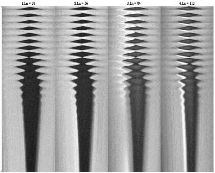
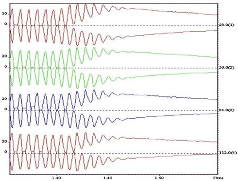
The VF contour detection algorithm comprises two main steps: i) defining an initial contour of the glottal area opening using an adaptive threshold; and ii) a refining iterative procedure, based on active contours applied to the region, to obtain the final segmentation. The control parameters which drive both steps are automatically determined by the programme. However, the user can manually adjust some of the controls to obtain an improved segmentation using a set of controls available in the user interface (Figure 20). The software allows selection of the desired frame(s) to be processed [51].
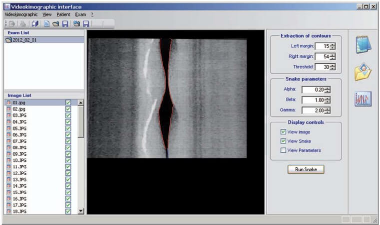
Once the final contour has been obtained, the parameters of interest are evaluated. The software is designed to give a value of each parameter for each video frame by averaging the parameters over all the vibration periods, which can be observed on the frame. This reduces the variability of the results by smoothing out noise and eases the management of data by giving a fixed number of values for a given video sequence in- dependently from the acquisition. The results can be exported in text mode for further elaboration or plotted on a line graph. The programme has been specifically adapted for this research in order to save the required parameters that are evaluated for each frame (for instance, left and right amplitudes, in addition to amplitude ratio).
However, the segmentation of the glottal area has been shown to be a difficult task requiring varying degrees of user interaction. This is a rapidly evolving field of research. Recently, Kist et al. [52] developed a deep learning enhanced novel software tool for laryngeal dynamics analysis, and provide pretrained deep neural networks for fully automatic glottal segmentation. Another current and promising research field in VF imaging is dynamic 2D magnetic resonance. Fischer et al. [53] succeeded in obtaining dynamic images of the periodic motion of the vocal folds during phonation in vivo at pitches of 150 and 165 Hz, with a temporal resolution of about 600 µs. The dynamic image information correlates well with the oscillation phases from the EGG-signal, and the open and closed phase can be clearly distinguished.
5. Suggestions for Future Work
Several research topics could benefit from polygraphic recordings with the parameters such as described and analysed in this article: examples are particular phonation modes or phonatory ‘accidents’ in trained vocalists, various types of diplophonia, register breaks, inspiratory phonation, ventricular phonation, comparing MADR and MFDR in various emission conditions, etc. Another field pertains to vocal fold behaviour during wind instrument playing. Voice onset is considered as a critical moment of phonation that deserves particular attention: it is a dynamic transient event, in which the forces in play progressively adjust until a steady state is reached. The methods analyzed in this article are particularly well suited for an in depth investigation of voice onset, specifically in acting and singing voice.
The photometric procedure for monitoring glottal area has many important advantages, but its application is limited to trained vocalists and to sustained vowels. High speed video with high definition by means of a transnasal flexible scope and automatic image processing could provide comparable signals (including differentiation) in voice professionals (like singers), and in voice patients, e.g., for damping studies.
REFERENCES
[1] K.
Ishizaka, J.L. Flanagan “Synthesis of voiced sounds from a two-mass model of
vocal cords.” Bell Syst Tech J, vol. 51, no. 6, pp. 1233-1268,
1972. View at: Publisher
Site
[2] I.R.
Titze “The human vocal cords: A mathematical model.” Phonetica, vol. 29,
no. 1, pp. 1-21, 1974.
View at: Publisher Site | PubMed
[3] I.R.
Titze “The physics of small-amplitude oscillation of the vocal folds.” J
Acoust Soc Am, vol. 83, no. 4, pp. 1536-1552, 1988. View at: Publisher Site | PubMed
[4] P.H. DeJonckere, M. Kob
“Pathogenesis of vocal fold nodules: new insights from a modelling approach.” Folia Phoniatr Logop, vol.
61, no. 3, pp. 171-179, 2009. View at: Publisher Site | PubMed
[5] J Jaromír Horáček, Vojtěch Radolf, Vítězslav Bula, et al. “Experimental modelling and human data
of glottal area declination rate for vowel and semi-occluded vocal tract
phonation.” Biomedical Signal Processing and Control, vol. 66, pp.
102432, 2021. View at: Publisher Site
[6] Philippe
H Dejonckere, Jean Lebacq, Leonardo Bocchi, et al. “Automated tracking of
quantitative parameters from single line scanning of vocal folds: a case study
of the ‘messa di voce’ exercise.” Logoped Phoniatr Vocol, vol. 40, no.
1, pp. 44-54. View at: Publisher Site | PubMed
[7] Philippe
Henri DeJonckere, Jean Lebacq 2, Ingo R Titze, “Dynamics of the driving force
during the normal vocal fold vibration cycle.” J Voice, vol. 31, no. 6,
pp. 714-721, 2017. View
at: Publisher
Site | PubMed
[8] P.H. DeJonckere, J. Lebacq “Quantification
of the intraglottal pressure during the modal vibration cycle. In: Models and
Analysis of Vocal Emissions for Biomedical Applications: 10th International
Workshop December 13-15, 2017.” Firenze University Press, pp. 111−114,
2017.
[9] P.H.
DeJonckere, J Lebacq, “Damping of vocal fold oscillation at voice offset.” Biomedical
Signal Processing and Control, vol. 37, pp. 92-99, 2017. View at: Publisher Site
[10]
J. Lebacq, P. H. DeJonckere, “The
dynamics of vocal onset.” Biomedical Signal Processing and Control, vol.
49 pp. 528-539, 2019. View
at: Publisher
Site
[11]
Philippe H DeJonckere, Jean Lebacq, “In
Vivo Quantification of the Intraglottal Pressure: Modal Phonation and Voice
Onset.” J Voice, vol. 34, no. 4, pp. 645.e19-.645.e39, 2020. View at: Publisher Site | PubMed
[12]
I.R. Titze “Principles of Voice
Production. 2nd Printing.” Iowa City, IA: National Center for Voice and Speech,
2000.
[13] Robert J
Stachler 1, David O Francis 2, Seth R Schwartz, “Clinical
Practice Guideline: Hoarseness (Dysphonia) (Update).” Otolaryngol Head Neck Surg, vol. 158, no. 1_suppl, pp. S1-S42,
2018. View at: Publisher
Site | PubMed
[14]
P.H. DeJonckere, H. Versnel
“High-speed imaging of vocal fold vibration: analysis by four synchronous
single-line scans of onset, offset and register break.” in: D. Passali (Ed.),
Proceedings of the XVIII I.F.O.S. (International Federation of
Oto-rhino-laryngological Societies) World Congress, pp. 1-8, 2005.
[15] O Köster, B Marx, P Gemmar, et al.
“Qualitative and quantitative analysis of voice onset by means of a
multidimensional voice analysis system (MVAS) using high-speed imaging.” J
Voice, vol. 13, no. 3, pp. 355-374, 1999. View at: Publisher Site | PubMed
[16]
D. Deliyski “Laryngeal high-speed
videoendoscopy.” in: K.A. Kendall, R.J.Leonard (Eds.), Laryngeal Evaluation,
Georg Thieme Verlag, Stuttgart, 2010.
[17]
Matthias Echternach, Michael
Döllinger, Johan Sundberg, “Vocal fold vibrations at high soprano fundamental
frequencies.” J Acoust Soc Am, vol. 133, no. 2, pp. EL82-EL87, 2013. View at: Publisher Site | PubMed
[18]
D.D. Mehta , D.D. Deliysky, S.M.
Zeitels, et al. “Integration of transnasal fiberoptic high-speed videoendoscopy
with time-synchronized recordings of vocal function.” in: K. Izdebski (Ed.),
Normal and Abnormal Vocal Folds Kinematics: High Speed Digital Phonoscopy
(HSDP), Optical Coherence Tomography (OCT) & Narrow Band Imaging (NBI®),
vol. I, Technology, CreateSpace Independent Publishing Platform, SanFrancisco,
2015. San Francisco: Pacific Voice & Speech Foundation edition, pp.
105-114.
[19] Hamzeh Ghasemzadeh, Dimitar D
Deliyski, Robert E Hillman, et al. “Method for Horizontal Calibration of
Laser-Projection Transnasal Fiberoptic High-Speed Videoendoscopy.” Appl Sci
(Basel), vol. 11, no. 2, pp. 822, 2021. View at: Publisher Site | PubMed
[20] Hamzeh
Ghasemzadeh, Dimitar D Deliyski “Non-Linear Image Distortions in Flexible Fiberoptic Endoscopes and
their Effects on Calibrated Horizontal Measurements Using High-Speed
Videoendoscopy.” J Voice, vol. 36, no. 6, pp. 755-769, 2022. View at: Publisher Site | PubMed
[21] J G Svec, H K Schutte “Videokymography:
high-speed line scanning of vocal fold vibration.” J Voice, vol. 10 no.
2, pp. 201-205, 1996. View at: Publisher Site | PubMed
[22]
F.
Sram, J. Svec, J. Vydrova, “Videokymography.” in: A.
Zehnhoff-Dinnesen, B. Wiskirska-Woznica, K. Neumann, T. Nawka (Eds.), European
Manual of Medicine. Phoniatrics, vol. I, Springer-Verlag, Berlin, Heidelberg,
pp. 379-387, 2020.
[23]
Anne-Maria
Laukkanen, Ahmed Geneid, Vítězslav Bula,et al. “How Much
Loading Does Water Resistance Voice Therapy Impose on the Vocal Folds? An
Experimental Human Study.” J Voice, vol. 34, no. 3, pp. 387-397, 2020. View at: Publisher Site | PubMed
[24] Bruce R. Gerratt, David G. Hanson,
Gerald S. Berke, “Photoglottography: a clinical synopsis.” J Voice, vol.
5, no. 2, pp 98-105, 1991. View at: Publisher Site
[25] P.H. DeJonckere “Instrumental methods
for assessment of laryngeal phonatory function.” In A.
Zehnhoff-Dinnesen, B. Wirskirska-Woznica, K. Neumann T. Nawka (Eds.) European Manual of Medicine.
Phoniatrics, , Springer Verlag, Berlin Heidelberg, vol. 1, pp. 396-405, 2020.
[26] P
H DeJonckere “Comparison of two methods of photoglottography in relation to
electroglottography.” Folia
Phoniatr (Basel),
vol. 33, no. 6, pp. 338-347, 1981. View at: Publisher Site | PubMed
[27] A J Fourcin E. Abberton “First
applications of a new laryngograph.” Volta Rev, vol. 69, pp. 507-508,
1972.
[28] J. N. Sarvaiya, P.C. Pandey, V.K.
Pandey “An impedance detector for glottography.” IETE J. Res, vol. 55
pp. 100-105, 2011.
[29] M. Rothenberg “A new
inverse-filtering technique for deriving the glottal airflow waveform during
voicing.” J Acoust Soc Am, vol. 53, no. 6, pp. 1632-1645, 1973. View at:
Publisher Site | PubMed
[30] M. Rothenberg “Measurement of Airflow
in Speech.” J Speech Hear Res, vol. 20, no. 1, pp. 155-176, 1977. View
at: Publisher Site | PubMed
[31]
M. Rothenberg “Source-tract acoustic
interaction in breathy voice.” In: Titze IR, Scherer RC Eds.) Vocal Fold
Physiology: Biomechanics, Acoustics and Phonatory Control. Denver, CO: The
Denver Center for the Performing Arts, pp. 465-481, 1984.
[32] P. Badin, S Hertegard, S, I Karlsson
“Notes on the Rothenberg mask.” Dept. for Speech, Music and Hearing
Quarterly Progress and Status Report, vol. 31, no. 1, pp. 1-7, 1990.
[33] P. Alku “Glottal
inverse filtering analysis of human voice production. A review of estimation
and parameterization methods of the glottal excitation and their applications.” Sadhana, vol. 36, no. 5, pp. 623-650, 2011.
[34]
O Schindler, M L Gonella, R Pisani
“Doppler ultrasound examination of the vibration speed of vocal folds.” Folia
Phoniatr (Basel), vol. 42, no. 5, 265-272, 1990. View at: Publisher Site | PubMed
[35]
W. Angerstein “Sonographic
examination of the larynx.” in: A. Zehnhoff-Dinnesen, B. Wiskirska-Woznica, K.
Neumann, T. Nawka (Eds.), European Manual of Medicine. Phoniatrics, vol. I,
Springer-Verlag, Berlin, Heidelberg, pp. 416 -418, 2020.
[36] J J Jiang, I R Titze “Measurement
of vocal fold intraglottal pressure and impact stress.” J Voice, vol. 8, no. 2, pp. 132-144, 1994.
View at: Publisher
Site | PubMed
[37] J Jiang, T O'Mara, D Conley, et al.
“Phonation threshold pressure measurements during phonation by airflow
interruption.” Laryngoscope, vol. 109, no. 3, pp. 425-432, 1999. View
at: Publisher
Site | PubMed
[38] S Hertegård, J Gauffin, P A Lindestad
“A comparison of subglottal and intraoral pressure measurements during
phonation.” J Voice, vol. 9, no. 2, pp. 149-155, 1995. View at: Publisher Site | PubMed
[39] Jan G Švec, Svante Granqvist
“Tutorial and Guidelines on Measurement of Sound Pressure Level in Voice and
Speech.” J Speech Lang Hear Res, vol. 61, no. 3, pp. 441-461, 2018. View
at: Publisher
Site | PubMed
[40] Claudia
Manfredi, Philippe H Dejonckere “Voice dosimetry and monitoring, with emphasis
on professional voice diseases: Critical review and framework for future
research.” Logoped Phoniatr Vocol, vol. 41, no. 2, pp. 49-65, 2016. View at: Publisher Site | PubMed
[41] Jean
Lebacq, Jean Schoentgen, Giovanna Cantarella, et al. “Maximal Ambient Noise
Levels and Type of Voice Material Required for Valid Use of Smartphones in
Clinical Voice Research.”
J Voice, vol. 31, no. 5, pp. 550-556, 2017. View at: Publisher Site | PubMed
[42]
Philippe Henri DeJonckere, Jean
Lebacq “Vocal Fold Collision Speed in vivo: The Effect of Loudness.” J
Voice, 36, no. 5, pp. 608-621, 2020. View at: Publisher Site | PubMed
[43] I R Titze “Acoustic interpretation of
the resonant voice.” J Voice, vol. 15, no. 4, pp. 519-528, 2001. View
at: Publisher
Site | PubMed
[44] Sheng Li, Ronald C Scherer, Lewis P
Fulcher, “Effects of vertical glottal duct length on intraglottal pressures and
phonation threshold pressure in the uniform glottis.” J Voice, vol. 32,
no. 1, pp. 8-22, 2018. View at: Publisher Site | PubMed
[45]
Sören Fex, Bibi Fex, Minoru Hirano “A
clinical procedure for linear measurement at the vocal fold level.” J Voice,
vol. 5, no. 4, pp. 328-331, 1991. View at: Publisher Site
[46] Hans Larsson, Stellan Hertegård
“Vocal fold dimensions in professional opera singers as measured by means of
laser triangulation.” J Voice, vol. 22, no. 6, pp. 734-739, 2008. View
at: Publisher
Site | PubMed
[47]
Philippe
DeJonckere, Jean Lebacq “Intraglottal aerodynamics at vocal fold vibration
onset.” J Voice, vol. 35, no. 1, pp.
156.e23−156.e32, 2021.
View at: Publisher
Site | PubMed
[48] J. Horáček, V. Radolf, V. Bula, A.M.
Laukkanen, Experimental modelling of glottal area declination rate in vowel and
resonance tube phonation. In Models and Analysis of Vocal Emissions for
Biomedical Applications: 11th International Workshop, December, Claudia
Manfredi (ed.), published by Firenze University Press, pp. 205-207, 2019.
[49] Ingo R Titze “Theoretical analysis of
maximum flow declination rate versus maximum area declination rate in
phonation.” J Speech Lang Hear Res, vol. 49, no, 2, pp. 439-447, 2006.
View at: Publisher
Site | PubMed
[50]
Dimitar D Deliyski, Milen Shishkov,
Daryush D Mehta, “Laser-Calibrated
System for Transnasal Fiberoptic Laryngeal High-Speed Videoendoscopy.” J
Voice, vol. 35, no. 1, pp. 122-128, 2021. View at: Publisher Site | PubMed
[51] C.
Manfredi, L. Bocchi, G. Cantarella, et al. “Videokymographic image processing: objective parameters and
user-friendly interface. Biomed. Signal Process.” Control, vol. 7 pp.
192-201, 2012.
[52] Andreas M Kist 1, Pablo Gómez 1, Denis Dubrovskiy, et al. “A Deep Learning Enhanced Novel Software Tool for Laryngeal Dynamics Analysis.” J Speech Lang Hear Res, vol. 64, no. 6, pp. 1889-1903, 2021. View at: Publisher Site | PubMed
[53] Johannes Fischer, Ali Caglar Özen, Serhat Ilbey, et al. “Sub-millisecond 2D MRI of the vocal fold oscillation using single-point imaging with rapid encoding.” MAGMA, vol. 35, no. 2, pp. 301-310, 2022. View at: Publisher Site | PubMed
